


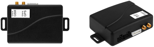
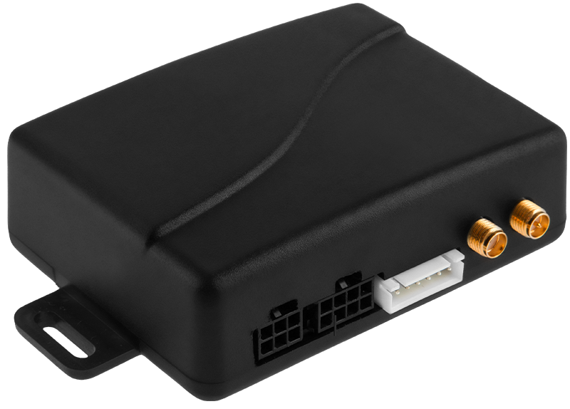
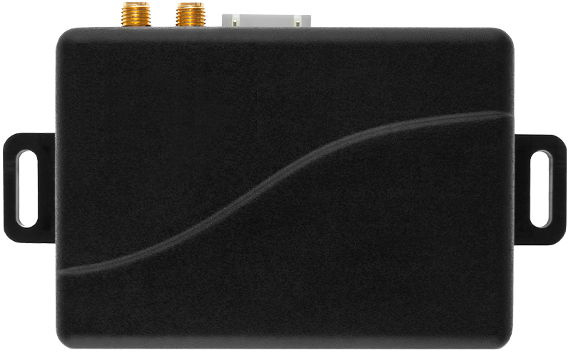
Terminal S10.3
Advanced logistics device with built-in internal battery and 3D sensor. It has external GSM / GPS antennas. A new version of the CAN module in a dedicated automotive version that reads information from the 1939/J1708/J1587/FMS/OBDII bus from almost 900 vehicles and machines. Ability to read DCT codes.
Available with 3 modem versions
- GPRS Modem Quectel 850/900/1800/1900 MHz with JAMMING DETECTION (dedicated EventID)
- GSM/EDGE/LTE Modem Quectel with JAMMING DETECTION (dedicated EventID), version EU LTE: B1/B3/B5/B7/B8/B20/B28 operating region EMEA GSM: B2/B3/B5/B8
- GSM/EDGE/LTE Modem Quectel with JAMMING DETECTION (dedicated EventID), version LA LTE: B2/B3/B4/B5/B7/B8/B28/B66 operating region Latin America GSM: B2/B3/B5/B8
GPS Quectel L76 receiver with ANTY-JAMMING and JAMMING DETECTION (dedicated EventID) function
Built-in module which read the data from the CAN bus (J1939/J1708/J1578/FMS/ OBDII) – over 900 vehicles and machines supported (Full CAN module description on a separate catalog card)
Ability to read DTC codes (Diagnostic Trouble Codes)
Possibility to read the status of the tachograph and drivers card numbers (on the off ignition as well!)
Maintaining the key operating parameters: time and GPS data - Data is never lost - even after a power cut
Advanced filters of analog inputs (analog floats; fuel probes) with data support after the loss of the main power supply
External active GPS antenna (3 meter / SMA connector)
External GSM/LTE antenna (3 meters / SMA-RP)
Internal sustaining clock RTC (Real Time Clock)
Communication port RS-232-TTL (optional: RS-232, RS-485)
Internal battery 500 mAh; charging control
ABS casing: 89x63x30 [mm]
Memory archive - minimum of 24.000 events (up to 48.000)
LED diods signifying the strenght of the GSM signal and the number of GPS satellites
Full support of 1-Wire DALLAS protocol (6 thermometers, DALLAS / RFID identification)
Alarm, which informs that the GPS antenna is dissconnected - real-time monitoring
Operating a dedicated Albatross Wi-Fi module which enables a communication between GPRS-S8 terminal and a communicator / tablet using Wi-Fi networks
Full support for Mobileye technology
Full solutions support MIDAS MOVON
Authoring solution of protecting inputs of the device (power; ignition switch; analog inputs) - these inputs are damage resistant (e.g surge in vehicle installation)
Incremental firmware - backward compatible always contains all the device functions , which ensures ease of managing software versions; Files to update are delivered directly to a partner in order to further updates by using the FTP server
Open communication protocol and remote support of engineers in real time (Skype) facilitates the process of implementation; Record implementation of the protocol took place in a few days!
3D sensor support to detect an accident; towing; car crash
ImmoDALLAS - an additional security for customers vehicle. The device activates the output in case of detecting the absence of authorization (DALLAS, RFID); The device allows you to save up to 2047 identification numbers of drivers!
Ignition signal detection using a dedicated analog input, the main power supply voltage or from CAN bus
Ability to implement a dedicated logic functions; commands and a help of handling modules on partners demand in case of further cooperation
Possibility of connecting Garmin navigation using the signal converter RS-232 to RS-232-TTL
GSM code of the currently logged in GSM operator
Working status of the GPS receiver (correct / incorrect)
Dedicated montage schemes for every vehicle (CAN)
Counting mileage based on data from the GPS
Cost control of the SIM card
Daily limit for GPRS/LTE connections in the roaming and home network
Daily SMS limit
Additional algorithm stabilizing analog measurements of fuel
SIMHOLDER in a drawer version:
- As standard, the terminal is equipped with a 2FF - MINI SIM drawer (the same size as in the S8 series terminals)
- Option to buy the 3FF - MICRO SIM drawer (Q3 2022)
Power supply of thermometers and accessories from JP3 connector can be controlled (possibility to make hard reset of accessories from S10 Terminal)
Individual device configuration
Dedicated commands, functions
Individual device casing
Individual device identification
Over 60 logistic informations reading from CAN bus
Over 30 CAN indicators (checkengine, lights, belts, airbag...)
Sudden acceleration, sudden breakings
Advanced ECODRIVING module
Fully automatic vehicle synchronization procedure
Data from tachograph - current STATUS
Driver identification from tachograph


Technical specifications
System supply from + 8V to + 31V
The average value of power consumption.
Offline terminal (5 minutes after the ignition is turned off):
29 mA +/- 5% for power supply=12.7V
20 mA +/- 5% for power supply=25.4V
Online terminal (Ignition is on):
54 mA +/- 5% for power supply=12.7V
32 mA +/- 5% for power supply=25.4V
Terminal in SLEEPMODE:
< 5 mA +/- 5% for power supply=12.7V
< 3 mA +/- 5% for power supply=25.4V
Operating temperature -30°C to + 85°C
Inputs / Outputs
2 reacting to mass inputs
3 open collector outputs
3 analog inputs (for ignition voltage measurement; fuel probes)
1-Wire Input (identification of drivers; temperature measurement; DALLAS, RFID)
RS-232-TTL communication port (default)
RS-232 communication port (optional)
RS-485 communication port (optional)
Counting input
CAN J1939/J1708/J1587/FMS/OBDII
Configuration
Remote: SMS, GPRS, TCP, programming application
Local (PC application + programming wire)
Tracking modes
8 self-contained tracking modes
(including the ignition signal)
Time mode
Distance considering mode
Separate settings for network Roaming
JP-1 connector description
1. The main power supply input (8V - 31V)
2. Open collector output (300 mA)
3. Ignition signal input (+)
4. Input (-)
5. Input (+) / analog measurement 0-32V
6. Main mass input. (GND)
JP-2 connector description
1. Input (-)
2. Open collector output (300 mA)
3. CAN-H input - CAN J1939/CAN-TACHO input*
4. CAN-L input - CAN J1939/CAN-TACHO input*
5. CAN2-H input - CAN J1939/J1708/J1578/FMS/OBDII/CAN-TACHO input*
6. CAN2-L input - CAN J1939/J1708/J1578/FMS/OBDII/CAN-TACHO input*
7. Counting input
8. Input (+) / analog measurement 0-32V
* a detailed description of the input in the installation manual
JP-3 connector description
1. Mass (GND)
2. TxD (for RS communication needs)
3. RxD (for RS communication needs)
4. Supply voltage for the Dallas (3.7V) thermometer
5. Input 1-Wire (identification of drivers and temperature measurement)
6. Power supply 3.3V (LED Dallas reader diod)