icon

Terminal S10.5 - methods of connecting to the CAN bus

icon 2024-02-14

Learn about the functionality of our terminals
Terminal S10.5 - methods of connecting to the CAN bus

Terminal S10.5 is an advanced logistics device with a built-in internal battery and a 3D sensor, equipped with external GSM/GPS antennas. As part of the 10 series, a new version of the CAN module has been introduced, specifically designed for automotive applications (supporting CAN-FD). This module allows for reading information from the 1939/J1708/J1587/FMS/OBDII bus of over 900 vehicles and machines.

Additionally, the terminal features a Tachograph Memory Reader module, enabling the monitoring of the drivers working hours and the downloading of DDD files from digital tachographs. Its worth noting that both mentioned modules have been integrated into a single processor, which constitutes a significant difference between the 10 series and the 8 series.

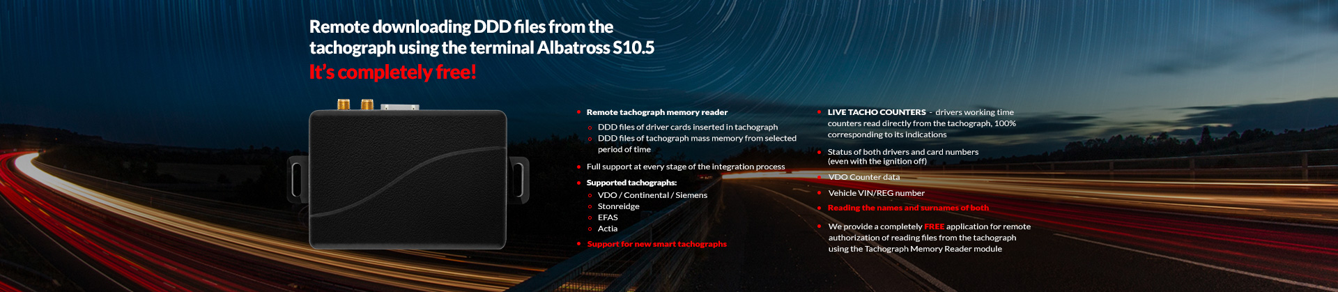
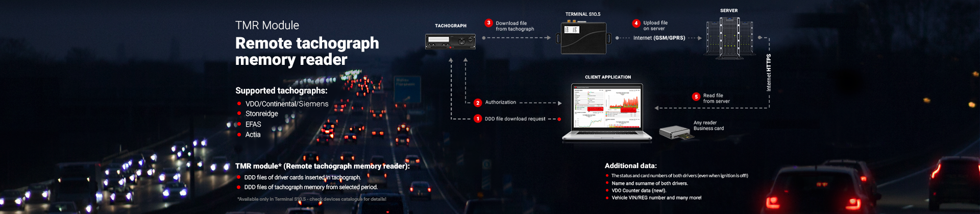
The S10.5 terminal is equipped with two twisted pair outputs, designed for both reading logistic data from the CAN bus and remotely downloading DDD files. Nevertheless, there are specific conditions under which it is recommended to connect both twisted pairs, while in other situations, one is sufficient. All possibilities are detailed in the next part of this newsletter.

In what cases should only the orange twisted pair be connected?

In the case of the S10.5 terminal, reading logistic data and downloading DDD files can be achieved using only one twisted pair - orange/brown or orange/green - when the CAN module connection diagram for a specific vehicle model indicates the connection of this twisted pair to pins C5/C7 of the digital tachograph. Alternatively, this setup is applicable when opting to use the FMS connector as the connection to the bus.

The above two variants result in the green twisted pair remaining unconnected to any bus. In the case of such a connection variant, there is no need for additional resistance verification, which is performed when the green twisted pair is intended to be connected to the bus.

In what cases should the orange and green twisted pairs be connected?

Connecting both twisted pairs - orange/brown, orange/green, as well as green/black, green/white - is necessary when the CAN module connection diagram for a specific vehicle model does not indicate the connection of the orange twisted pair to pins C5/C7 of the digital tachograph, or when choosing not to use the FMS connector as the connection to the bus.

In such a situation, the orange twisted pair is connected according to the diagram of the specific vehicle model, while the green twisted pair is connected directly to pins C5/C7 of the digital tachograph.

The use of the green twisted pair also requires measuring the resistance before proceeding with any installation work. The resistance between pins C5/C7 should be measured before connecting the green twisted pair, with the vehicle ignition turned off.

If the multimeter shows:

  • ~120 Ohms, then connect the green twisted pair to pins C5/C7 without additional actions because the resistance will result in approximately ~60 Ohms, considering the resistor soldered between the green/white and green/black wires.

  • ~60 Ohms, then connect the green twisted pair to pins C5/C7 and remove the resistor between the green/black and green/white wires. This will result in a resistance of ~60 Ohms.

  • 1k Ohm (>1000 Ohms), then connect the green twisted pair to pins C5/C7 and create a bridge between pins C7/C8. This will result in a resistance of ~60 Ohms.

The above actions are aimed at achieving a result where, after completing the installation process, the resistance will be 60 ohms with the terminal connected to the tachograph.

Terminal S10.5
Installation manual

Do you have more questions?
Contact our team!


icon   back